How are BIOS and UEFI different?
Why does everyone say 'go into BIOS' when modern machines use UEFI? Covers BIOS, UEFI, boot flow, Secure Boot, Boot#### and how firmware builds the system before the OS runs.
If you’ve ever built a PC, installed Windows, set up a dual-boot Linux system, or just searched online for why your machine won’t recognize a hard drive, you’ve almost certainly come across this advice:
“Go into BIOS and change the settings.”
It sounds simple. But what exactly is BIOS that every problem sends you there? You go into BIOS to change boot order, enable TPM, toggle Secure Boot, enable XMP for RAM, adjust fan curves, change SATA mode, disable USB booting — the list goes on and on.
If you used a computer before the early 2000s, you probably remember the screen: press Del or F2 right after power-on, and a blue or gray screen appears with white text. Arrow keys to navigate, Enter to select, + and - to change values. No mouse, no graphics, no animations. That was Legacy BIOS Setup.
But look closely at modern machines and you’ll notice something odd: most of them no longer use BIOS in the traditional sense. They use UEFI internally. Yet technicians, Windows users, PC builders, and even many engineers still call it “BIOS.”
So what is BIOS? What is UEFI? If modern machines use UEFI, why do we still say “go into BIOS”? And where do the two actually differ — beyond one looking older and one looking newer?
To answer this clearly, I want to start from the perspective that is most familiar to me: embedded firmware.
When I first moved from embedded development into PC firmware, I assumed BIOS and UEFI only differed in their UI. BIOS was the blue text screen. UEFI had mouse support, color graphics, and a more polished look.
After spending time reading boot logs, reading driver source code, and debugging issues like “the machine sees the SSD but it’s not in the boot menu,” I realized I had been looking at the wrong thing.
The real difference is not the UI.
It’s in how firmware organizes itself to build a PC from a state where almost nothing exists yet: RAM not initialized, chipset not configured, PCIe not enumerated, storage not visible, OS not there to help.
With embedded firmware, I was usually writing code for a system that already had a reasonably known shape. With BIOS/UEFI, firmware has to create that shape first — then hand it to the operating system.
This article starts with familiar things: booting from USB, Secure Boot, Windows Boot Manager, an SSD that doesn’t appear in the boot menu — and then works toward the architecture underneath. If you’re not yet familiar with concepts like Boot####, Device Path, Protocol, HII, or NVRAM, that’s fine. By the end of this article you’ll have a mental map. The linked notes below go deeper on each piece.
How PC firmware differs from typical embedded firmware
If you’ve worked in embedded, you know this model:
Power on
CPU/MCU starts executing from the reset vector
Reset handler
Copy .data, zero .bss, prepare the C environment
Run main
Initialize GPIO, UART, peripherals
Main loop / RTOS
Firmware begins running its main logic
The system already exists. Flash is there. RAM is there. You just write code to control them.
PC firmware — whether Legacy BIOS or UEFI — does not have those conditions. When the CPU first resets, nothing reliable exists: DRAM is not initialized, the chipset is not configured, nothing is enumerated, the OS is not there to help. Firmware must build the system before it can use the system.
Embedded firmware is like an operator running a factory that already exists.
PC firmware is like an engineer building that factory from scratch, making sure everything comes up in the right order, then handing it off.
This difference is rooted in hardware. A microcontroller typically integrates flash, RAM, and peripherals in one chip — power it on and it can run immediately. An x86 CPU is different. It needs external DRAM, a chipset, PCIe, storage controllers, and a long sequence of platform bring-up steps before an OS can run.
| Aspect | Embedded firmware | BIOS/UEFI |
|---|---|---|
| Environment at startup | Hardware is reasonably stable | Nearly empty. DRAM not initialized, chipset not configured |
| Main job | Control the device | Build the entire system, then hand it to the OS |
| Lifetime | Runs for the life of the device | Runs during boot, then transfers control to the OS |
| Architecture | Main loop / RTOS depending on the system | Multiple phases, multiple layers, its own driver model |
Looking at the boot path: two different approaches
The quickest way to see the difference between Legacy BIOS and UEFI is to look at how they boot.
Legacy BIOS does everything in a fairly linear sequence:
POST
Power-On Self Test, basic hardware checks
Find boot device
Scans the device list in priority order
Read boot sector
Reads the first 512 bytes of the device. First-stage boot code starts here
Run bootloader
First-stage bootloader in MBR loads the next stage
Enter OS
Control transfers to the kernel
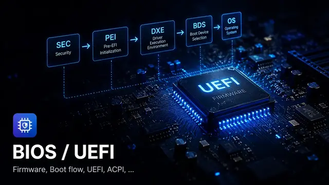
UEFI organizes boot into clear phases. Each phase has its own responsibilities and creates the foundation for the next:
Security Phase
CPU reset, temporary memory, earliest environment setup. Some platforms perform initial verification here
Pre-EFI Init
Initialize DRAM, build the HOB list, hand off data to DXE
Driver Execution
Load drivers, publish protocols, enumerate all devices
Boot Device Select
Read Boot####, resolve Device Path, load the OS loader
ExitBootServices
OS loader gets the memory map, calls EBS, hands control to the kernel
The difference is not just more steps. At each UEFI phase, the available resources are genuinely different.
SEC has no DRAM, so it cannot use the heap normally. PEI starts bringing up DRAM and passes information to DXE via HOBs. DXE is where the full driver model becomes available. BDS uses the protocols and boot variables already built by DXE to select and load the OS loader.
The phase structure is not there to add complexity. It’s the only way to organize a large platform starting from nearly nothing.
Legacy BIOS: got the job done, but couldn’t scale
Legacy BIOS served well for decades. It did exactly what was needed at the time: initialize basic hardware, run POST, find a boot device, read the MBR, and jump into the bootloader.
But its original design was not built to scale the way modern PCs needed:
- No standard driver model. Each vendor wrote their own, hard to reuse
- MBR partition scheme limited disks to under 2 TB with at most 4 primary partitions
- The boot sector was only 512 bytes
- Essentially no boot security; any code in the MBR could be executed
- Code was typically monolithic with no standard interfaces between components
- Extending to network boot, new storage, firmware updates, or security policy was messy
When you need to add network boot, RAID, Secure Boot, firmware capsule updates, and support hundreds of NVMe controller variants, the problems become visible. Legacy BIOS had no clean mechanism to extend in those ways.
UEFI: an architecture, not just a feature set
UEFI (Unified Extensible Firmware Interface) is not Legacy BIOS with extra features. It was redesigned from the ground up as a firmware platform with a proper driver model.
The core difference: in UEFI, firmware modules communicate with each other through protocols, identified by GUIDs.
For example, a storage driver can publish a Block I/O Protocol on a handle:
gBS->InstallProtocolInterface(
    &Handle,
    &gEfiBlockIoProtocolGuid,
    EFI_NATIVE_INTERFACE,
    &BlockIoProtocol
);
A filesystem driver or BDS can then find and use that protocol:
gBS->LocateProtocol(
    &gEfiBlockIoProtocolGuid,
    NULL,
    (VOID **)&BlockIo
);
The storage driver doesn’t need to know how the filesystem driver will use it. The filesystem driver doesn’t need to know whether the storage is SSD, NVMe, SATA, or USB. BDS doesn’t need to know which controller is underneath. It goes through published protocols.
This is what makes UEFI modular in a meaningful sense. Each layer only knows its interface.
What is the “BIOS Setup” screen, really?
Coming back to the everyday question: when you “go into BIOS” to change boot order, enable TPM, toggle Secure Boot, change SATA mode, or enable XMP — where exactly are you going?
On an older machine, it might genuinely be Legacy BIOS Setup. But on most modern hardware, it’s UEFI Setup. People still say “BIOS” by habit, but the architecture underneath is completely different.
In UEFI, the modern setup screen is typically built on an architecture called HII, Human Interface Infrastructure.
If Legacy BIOS Setup is a block of C code drawing directly to the screen, UEFI HII is a structured pipeline. It separates the form description, multilingual strings, storage, callbacks, and where values are ultimately saved.
Form source
Describes forms, questions, display conditions
String package
Multilingual display strings
HII Database
DXE driver installs form package into the database
Setup Browser
Reads IFR, renders UI, handles input
Backing storage
Temporary data or buffer mapped to settings
Persistent storage
Values saved through the UEFI variable path
The nice thing about HII: each DXE driver can add its own forms to Setup without touching the Setup Browser code. The Browser just reads the HII Database and renders. It doesn’t need to know how many drivers are contributing forms.
This is why a modern laptop or server Setup menu can have hundreds of options organized across many tabs and submenus, while the codebase still has a clear structure.
From a Setup option to NVRAM
When you enter Setup and change an option — switching SATA Mode from AHCI to RAID, for example — that’s not simply a UI update.
Underneath, that option is typically mapped to a field in a VarStore. When the user saves, firmware must write the new value to NVRAM or equivalent storage. On the next boot, a PEI or DXE driver reads that setting back and configures the controller accordingly.
Change option
For example, switch SATA Mode to RAID
Hold temporarily
Setup Browser updates browser storage; may not write NVRAM immediately
Validate / notify
Driver can handle callback if it registered Config Access
Save & Exit
Browser calls RouteConfig() on the driver owning the FormSet
SetVariable()
Driver writes the setting to variable store
PEI/DXE reads back
Consumer reads the setting and configures hardware
The easy-to-miss step: the Browser does not necessarily write NVRAM the moment the user changes an option. Many flows hold the value in a temporary buffer. Only on Save & Exit does RouteConfig() and SetVariable() actually commit the data.
If SetVariable() fails, the UI may show the new value, but NVRAM still holds the old one. After a reset, everything goes back to before.
Where the differences show up in real artifacts
The architectural difference between Legacy BIOS and UEFI appears clearly in the things you actually encounter when working with these systems:
| Artifact | Legacy BIOS | UEFI |
|---|---|---|
| Boot target | MBR boot sector, 512 bytes | .efi file on the ESP (EFI System Partition) |
| Boot metadata | Simple priority list in firmware setup / old-style NVRAM | Boot#### variables in NVRAM, BootOrder, BootNext. Readable and writable through the UEFI API |
| Partition scheme | MBR, max 4 primary partitions, limited to 2 TB | GPT, far beyond MBR's practical limits. Most systems default to 128 partition entries and the layout can be extended |
| Driver/extension model | Option ROM, vendor-specific, non-standard | Protocol + Driver Binding, standardized, easier to extend |
| Setup UI | Monolithic setup, classic text interface | HII, VFR/IFR, String Package, FormSet, VarStore, Config Access |
| Persistent settings | CMOS/NVRAM, platform-specific | UEFI variable store, SetVariable/GetVariable, policy and SMM path depending on implementation |
| Boot security | Very limited | Secure Boot, db/dbx/PK/KEK, Measured Boot, TPM integration |
| Runtime after boot | Interrupt-based BIOS services, very limited | Runtime Services like GetVariable, SetVariable, GetTime remain available after ExitBootServices |
How Windows, Linux, and macOS relate to UEFI
These are not just details in a spec. They appear directly in the operating systems you use every day.
Windows surfaces UEFI through Windows Boot Manager, Secure Boot, TPM, Boot####/BootOrder, and the ESP partition. When you see “Windows Boot Manager” in the boot menu, when you toggle Secure Boot in firmware setup, or when Windows won’t boot after cloning a disk — you’re debugging UEFI artifacts, not just Windows.
Linux surfaces UEFI through GRUB, systemd-boot, shim, efibootmgr, the ESP, and EFI boot stubs. A Linux installation may boot through a bootloader like GRUB, or in some configurations the kernel itself has an EFI boot stub so firmware loads it directly as an EFI application. When a dual-boot breaks GRUB, when Secure Boot blocks a kernel or module, or when efibootmgr can’t write Boot#### — the problem sits at the boundary between Linux and UEFI firmware.
macOS needs a clear distinction: Intel Macs have a boot process closer to EFI, while Apple Silicon uses Apple’s own boot chain with its own Boot ROM and security policy. It shouldn’t be described as standard PC UEFI. But macOS still illustrates the same underlying principle: before the OS runs, there’s always a firmware/security chain responsible for verification, environment setup, and the handoff.
UEFI is not something only firmware engineers encounter. Windows users hit it when dealing with Secure Boot or Windows Boot Manager. Linux users hit it with dual-boot, shim, ESP, or efibootmgr. Different implementations, but the same underlying problem: firmware must establish a trustworthy boot path before the OS is allowed to run.
Quick comparison
| Criterion | Legacy BIOS | UEFI |
|---|---|---|
| Architecture | Monolithic | Phase-based, modular |
| Driver model | No standard | Protocol + Driver Binding |
| Boot | MBR boot sector | EFI application, Boot Manager |
| Disk | MBR-limited | GPT, far beyond MBR’s practical limits |
| Setup UI | Classic text setup | HII, VFR/IFR, Setup Browser |
| Setting storage | CMOS/NVRAM, platform-specific | UEFI variable, VarStore, NVRAM |
| Security | Very limited | Secure Boot, Measured Boot, TPM |
| Extensibility | Hard to extend | Protocols enable modular extension |
| Source structure | Hard to systematize | INF/DEC/DSC/FDF clearly structured in the EDK II world |
How the differences show up when debugging
This is what I find most important — understanding the architecture only has value if it changes how you approach problems.
Case 1: Machine won’t boot after cloning a disk
With a Legacy BIOS mindset, you check whether the MBR is valid and whether the partition is active.
With a UEFI mindset, you check: was the ESP created correctly on the new disk? Does the Boot#### in NVRAM have a Device Path pointing to the correct disk and partition? When you clone or restore a disk, the GPT partition GUID or device path may change or be duplicated. The old Boot#### still references the old Device Path, so the boot option becomes stale.
Case 2: Device is present but doesn’t appear in the boot menu
With a Legacy BIOS mindset, you check whether the disk is a boot device.
With a UEFI mindset, you trace the chain: did the bus driver enumerate the device and create a child handle? Was Block I/O Protocol published? Did the partition driver bind and create a partition handle? Did the filesystem driver install Simple File System Protocol? Did BDS find a handle with SFSP?
Find where the chain broke and fix it there.
Case 3: Setting saved in BIOS but lost after reboot
With a Legacy BIOS mindset, you think about the CMOS battery or CMOS clear.
With a UEFI mindset, you think about the NVRAM variable store and the HII save flow: did RouteConfig() run? Did SetVariable() return an error? Do the variable attributes match what’s needed? Is the variable store full? Is a platform policy blocking the write? Is the SMM variable path working correctly? Is the consumer actually reading the right GUID, name, and offset?
Case 4: Added one new option and the machine can’t see its hard drive
This is a very firmware-specific case. The UI still shows the option normally, the build has no errors, the flash succeeded, the machine still enters Setup. But after reboot, storage behavior is wrong.
At this point, don’t just look at the UI. Check the struct layout, VarStore offsets, old NVRAM data, the default path, and the module that actually reads that setting. A single byte shift in SETUP_DATA can cause an entirely different field to be misread as SATA mode, TPM flag, or boot policy.
The first three cases help you see how UEFI differs from Legacy BIOS in the boot path. The fourth shows that “changing a BIOS setting” in UEFI goes through a fairly long pipeline: UI → HII → VarStore → callback → NVRAM → consumer.
Why should embedded engineers care?
If you only work with STM32 or simple MCUs, UEFI may not be directly relevant. But if you write firmware for POS terminals, kiosks, payment devices, industrial PCs, thin clients, mini PCs, or any x86-based system, this is day-to-day working knowledge.
Even for pure embedded work, understanding how UEFI organizes firmware helps you think better about:
- Bootloader staging: separating early init from main firmware, similar to the SEC/PEI boundary
- Memory init sequence: what you can and cannot do before having a full stack
- Driver init order: dependencies between drivers, similar to DEPEX in UEFI
- Interface-first design: coding against protocols rather than direct calls, making implementations swappable
- Persistent config: settings are not just global variables; they need storage, versioning, and migration
- Cross-stage handoff: the HOB pattern, passing data across boundaries safely
These patterns are not UEFI-specific. They are ways to organize complex firmware systematically. UEFI is one of the largest and best-documented examples of doing this at scale.
Common misconceptions
“UEFI is just BIOS with a nicer UI”
The UI is the smallest part. The real differences are the driver model, protocol system, boot manager, HII, NVRAM variables, and source organization. You can write UEFI firmware with no graphical UI at all and it’s still fully UEFI.
“Going into BIOS means directly configuring hardware”
Not exactly. In modern UEFI, you’re usually editing a setting in the Setup UI. That setting is saved to NVRAM or equivalent storage. On the next boot, a PEI or DXE driver reads it and then configures the hardware. The UI is just the visible layer.
“BIOS/UEFI has nothing to do with embedded”
If you only work with simple MCUs, true. But if you do bring-up for x86 boards or write firmware for devices running on a PC platform, this is working knowledge. Even for pure embedded, boot staging, config storage, driver dependency, and cross-stage handoffs are patterns worth knowing.
“Learning UEFI just means learning the boot flow”
Boot flow is the starting point. But working with UEFI in practice requires understanding more layers: Protocol, Handle Database, GUID, Driver Model, Boot Services, Runtime Services, HII/Setup, NVRAM variables, Device Path, and SMM. Each layer has its own debug approach. Boot flow tells you the sequence; it doesn’t tell you where things break or why.
Learning from the debug perspective
Many UEFI resources start from the spec and its definitions. That’s correct, but slow — especially when you have a machine that won’t boot and you need to understand what’s happening.
What I’ve found more effective is starting from a real debug question:
- “Why is this device in the system but not in the boot menu?”
- “Why does this setting save and then disappear after reboot?”
- “Why does the machine reset-loop after flashing new firmware?”
- “Why did adding one small Setup option change storage behavior?”
Each question leads you to exactly the layer you need to understand. When you understand why something breaks, you also understand how it’s supposed to work.
Looking back, the most important thing wasn’t memorizing how many phases UEFI has or what Legacy BIOS’s limitations were.
It was a shift in perspective:
In embedded, we write firmware for a system that already exists.
In PC firmware, the firmware is what creates that system.
And in modern UEFI, the screen everyone calls “BIOS” is just a small door into a much larger architecture behind it.
References
- UEFI Specification
- EDK II Project
- EDK II HII Database modules
- Linux kernel EFI stub documentation
- Microsoft Secure Boot overview
Read next
- UEFI Boot Flow: from Reset Vector to ExitBootServices
- DXE Phase: Drivers, Protocols, and how to read logs when nothing runs
- BIOS Setup, HII, and how NVRAM works
- What is SEC?
- What is PEI?
- What is DXE?
- What is BDS?
- What is a Protocol?
- What is the Handle Database?
Found this useful?
Save it or share it with someone learning firmware, BIOS/UEFI, and embedded systems.
Nội dung liên quan
Một số bài viết, ghi chú hoặc project có liên quan đến nội dung bạn vừa đọc.
What is BIOS Setup: from the classic blue screen to HII and modern NVRAM
Modern BIOS Setup is built on HII: VFR, VarStore, NVRAM. Why adding a field in the middle of a struct can break a system, and how to debug settings that don't persist.
UEFI Boot Flow: from Reset Vector to ExitBootServices
Not memorizing phase names — learning boot flow to know where a machine is dying and which direction to debug. From SEC through Runtime, a map for real failure modes.
What is ACPI: why firmware shouldn't power off by toggling a GPIO
Why shouldn't firmware toggle a GPIO to power off? ACPI is the contract firmware writes and the OS reads: tables, AML, power states, and debugging broken sleep and wake.
Đọc thêm về BIOS/UEFI
Khám phá các bài viết về BIOS/UEFI, embedded firmware, debugging và system-level thinking.