
Designing the Input Pipeline Before the USB Layer
How input flows from a keypad through scanning, debounce, key policy, and an event queue, and the tradeoffs made before an HID report ever gets built.
Post 4/8 in the series USB Device on STM32. This post isn’t about USB. It covers the internal firmware sitting behind the keyboard. If you only care about USB, feel free to skim it and jump ahead to post 5.
Before you read this
The previous post covered descriptors, how the host identifies a USB device. But with an HID keyboard, the descriptor only tells the host this is a keyboard. It says nothing about where firmware actually gets its key events from.
This post moves into real implementation, everything sitting before the USB layer: how firmware reads a 4x4 keypad, filters out contact noise, handles held keys and simultaneous presses, and produces clean, stable key events for the HID layer to consume later. This isn’t a GPIO tutorial, and it doesn’t go deep into HID reports either. Code snippets here are kept short, just enough to illustrate design decisions, not a line-by-line walkthrough.
Post 5 reuses the key event queue concept from this post without re-explaining it. Skip this one and jump straight to post 5, and the first few sections will throw some unfamiliar terms at you.
Key points
- The input pipeline splits into several small layers: scanning the keypad for a raw signal, filtering out contact bounce, tracking key state, building an event queue, and only then handing off to the HID layer.
- The timer interrupt doesn’t scan directly. The ISR just raises a scan request, and the real work happens in the main loop.
- Raw GPIO signal never goes straight to HID. It has to pass through a stabilization step first to filter out contact bounce and noise.
- A keypad without diodes isn’t a good fit for physical multi-key input. Firmware locks out input the moment it detects a simultaneous press, rather than trying to filter out “ghost keys” caused by current flowing backward through the matrix.
- The event queue is the boundary between the input layer and the HID layer, so HID never needs to know anything about GPIO details or the key processing underneath it.
Why bother with an input pipeline at all?
An HID keyboard report is just the end result. Before firmware can produce that report, it has to solve a handful of problems that have nothing to do with USB:
- What GPIO reads is just a raw voltage level at the moment it’s sampled.
- Mechanical contacts bounce, opening and closing rapidly several times before settling.
- A diode-less matrix keypad can suffer from ghosting when multiple keys are pressed at once.
- The USB layer shouldn’t depend directly on exactly when a GPIO scan happens.
- Behaviors like macro keys or key repeat need their own policy. They don’t belong stuffed inside a USB driver.
So firmware needs a middle layer, a pipeline that turns raw physical key signals into stable software events before the HID layer ever touches them.
Overview
Here’s the overall flow, from raw signal to a physical press or release turning into a software event:
Keypad matrix
Rows and columns, key signals from GPIOB.
rawState
A 16-bit bitmask: bit N means keyLoc N is currently pressed.
Stable state
Only accepts a change once the signal holds steady across two consecutive samples.
Repeat / Error
Held keys, simultaneous presses, or requiring all keys released.
KeyEvent_t
ON / OFF / REPEAT / ERROR.
HID layer
Post 5 turns this event into an HID report.
This post stops right at the queue: producing a key event and placing it in the queue. Turning that event into an HID report is covered in the next post.
Source map: what each module is responsible for
Here’s the full directory structure of the real STM32CubeIDE project that ships with this series.
The Hardware/ and Keyboard/ folders are what this post covers. Any file inside these two folders without a comment is out of scope for this post and gets covered in detail later, as the series builds up the USB layer.
Code CubeMX generates on its own also gets a comment, just aligned a little differently.
stm32g0-usb-device-lab/
├─ Core/                       // HAL init, system files generated by CubeMX
├─ Drivers/                    // CMSIS + STM32G0 HAL (vendor code)
├─ Middlewares/                // ST USB Device Library (vendor code)
├─ App/
│  └─ app_main.c                    // main loop: scan scheduler, KeyDetect_Run, HID convert
├─ Hardware/
│  ├─ keypad.c / keypad.h           // reads raw GPIO, returns a 16-bit rawState
│  └─ scan_scheduler.c / .h         // receives TIM6 ticks, raises scan requests for the main loop
├─ Keyboard/
│  ├─ key_detect.c / .h             // debounce, detects ON/OFF/REPEAT, simultaneous error handling
│  ├─ key_event_queue.c / .h        // holds KeyEvent_t for the HID layer downstream
│  ├─ key_table.c / .h              // separates physical keyLoc from what a key actually means
│  ├─ hid_keyboard_convert.c / .h
│  └─ hid_keyboard_report.c / .h
├─ Usb/
├─ USB_Device/                 // App + Target, descriptor and usbd_conf generated by CubeMX
└─ docs/
└─ tools/
Code snippets in this post are trimmed down to show how modules connect. The full source lives in the stm32g0-usb-device-lab repo.
Project conventions
The physical 4x4 keypad module I’m using comes with switches pre-labeled S1 through S16.
That’s just the manufacturer’s own numbering for the switches. It has nothing to do with the
order firmware scans the matrix in.
This series and its code don’t use the S1-S16 labels. Instead, everything is referred to by
keyLoc (0-15), numbered in exactly the order the matrix gets scanned:
keyLoc = row number x 4 + column numberThis convention is used consistently throughout the series, from how keys are referred to in text all the way to how they show up in demo videos. See the image below.
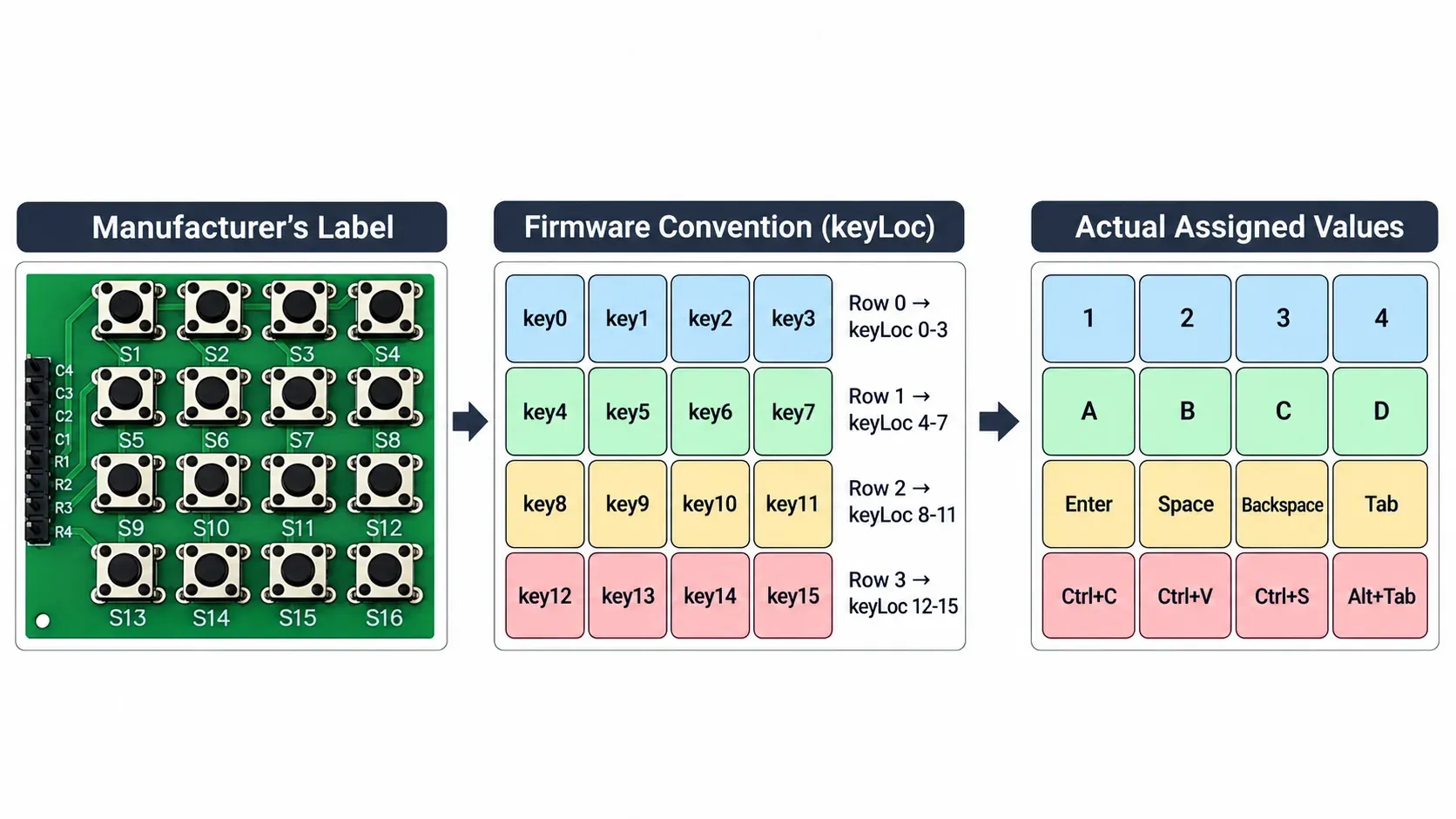
Here are all 16 real keys on this project, matching the sKeyTable struct defined in
key_table.c:
| Scan row | keyLoc | Assigned character |
|---|---|---|
| Row 0 | 0 - 1 - 2 - 3 | Number keys 1, 2, 3, 4 |
| Row 1 | 4 - 5 - 6 - 7 | Letters A, B, C, D |
| Row 2 | 8 - 9 - 10 - 11 | Enter, Space, Backspace, Tab |
| Row 3 | 12 - 13 - 14 - 15 | Macros: Ctrl+C, Ctrl+V, Ctrl+S, Alt+Tab |
The first three rows (keyLoc 0-11) are ordinary keys. Each press sends exactly one keycode, and they repeat while held.
The four keys on the last row (keyLoc 12-15) are one-shot macro keys. A single press fires an entire key combination right away, and they never repeat on hold. The reasoning and how that combination gets built belongs to the HID layer, and is covered in post 5. This post only covers their physical position in the matrix.
Decision 1: raw scan only returns a 16-bit bitmask
The GPIO layer shouldn’t know anything about debounce, macros, or HID. Its only job is to
read the keypad and return a 16-bit rawState, the instantaneous scan result, unprocessed.
Each bit represents one key’s state (0: released, 1: pressed), following this convention:
bit 0  = keyLoc 0
bit 1  = keyLoc 1
...
bit 15 = keyLoc 15
Here’s how to read or check a key’s state:
| Data | Meaning |
|---|---|
| rawState = 0x0000 | No key is currently pressed |
| rawState & (1 << 4) | keyLoc 4 is currently read as pressed |
| rawState has multiple bits set | Multiple keys are currently pressed at once |
If bit N is 1, that means keyLoc N was pressed at the moment of that scan. This layer doesn’t decide whether that’s a valid keypress or not. It just hands over raw data.
/* * KEYPAD_ROW_NUM = 4 * KEYPAD_COL_NUM = 4 *//* Trimmed down from Keypad_ReadRaw(), see the full version in the repo */uint16_t state = 0;for (row = 0; row < KEYPAD_ROW_NUM; row++) { KEYPAD_GPIO->BSRR = (uint32_t)sRowPins[row] << 16U; /* pull the row LOW */ for (col = 0; col < KEYPAD_COL_NUM; col++) { if ((KEYPAD_GPIO->IDR & sColPins[col]) == 0U) { /* check for a LOW column signal */ state |= (1U << (row * KEYPAD_COL_NUM + col)); /* update the matrix state */ } } KEYPAD_GPIO->BSRR = (uint32_t)sRowPins[row]; /* return the row to HIGH */}The STM32G0B1 code hits the BSRR/IDR registers directly instead of going through
HAL_GPIO_WritePin/ReadPin for this scan loop, purely to keep things fast and avoid any
overhead that could throw off scan timing.
I’ve already covered the bit layout and practical use of the BSRR and IDR registers in What Is STM32 GPIO Register Access?, so I won’t repeat that here.
Decision 2: the timer ISR only raises a request, it never scans directly
The easiest approach would be calling KeyDetect_Run() straight from the TIM6 ISR. But that
makes the ISR quite long, since that function has to scan the GPIO matrix, stabilize the key
signal, handle held keys, and push events into the queue. If USB interrupts or CDC/Vendor
handling later also need the CPU, an ISR that long makes the whole system harder to reason
about and harder to keep predictable.
So I went with this design instead:

Here’s the tradeoff between the two approaches:
| Approach | Pros | Cons |
|---|---|---|
| Scan directly inside the ISR | Perfectly even scan cadence, simpler code | Long ISR, hard to extend, can delay higher-priority interrupts like USB |
| ISR only raises a request (used here) | Short ISR, easy to reason about, doesn't block other interrupts | The main loop can't afford to block for too long, needs a way to shed load if it does |
Here’s the thing that matters: firmware isn’t just scanning a keypad. It also has USB interrupts, HID Interrupt IN transfers, and later CDC/Vendor traffic on top. Keeping the ISR short from the start makes the whole architecture easier to grow, not just for this keypad problem.
The number of pending scan requests is capped at 10. If the main loop is busy for more than 10 x 5 ms = 50 ms, the ticks after that get dropped instead of letting the counter grow without bound. Losing a rare scan cycle here and there is an acceptable price for keeping the system stable while the main loop is busy handling a USB transfer.
Decision 3: debounce over two consecutive samples
Raw GPIO signal isn’t trustworthy the instant it’s read, since mechanical contacts typically bounce for a few milliseconds. Firmware only confirms a change once the same state shows up in two consecutive scans. At a 5 ms scan interval:
t = 0ms    raw = 0
t = 5ms    raw = 1    a press just appeared, not confirmed yet
t = 10ms   raw = 1    stable across 2 samples → KEY_EVENT_ON
Releasing a key needs two consecutive samples of the released state too:
t = 0ms    raw = 1
t = 5ms    raw = 0    a release just appeared, not confirmed yet
t = 10ms raw = 0 stable across 2 samples → KEY_EVENT_OFF| Sample count | Latency | Tradeoff |
|---|---|---|
| 1 sample | 0ms (no filtering) | Nothing to compare against, the signal itself is genuinely unstable |
| 2 samples (used here) | 10ms | Filters real-world contact bounce well, low perceived input latency |
| 3 samples | 15ms | More robust against unusually long bounce, but adds 5ms of latency to every keypress |
Decision 4: the keypad doesn’t try to support multi-key input
The 4x4 keypad in this project has no anti-ghosting diodes. When multiple keys are pressed at once, firmware can’t always tell a real keypress apart from a ghost key caused by current leaking backward through neighboring closed switches, which makes the scan misread a key that was never actually pressed.
| Approach | Pros | Cons |
|---|---|---|
| Try to filter ghost keys in software | Looks like it supports more simultaneous keys | Complex, unreliable on a diode-less matrix |
| Lock input on simultaneous press (used here) | Simple, easy to reason about, safe | Doesn't support physical multi-key combinations |
This policy is deliberately conservative. Firmware doesn’t wait for the signal to stabilize before checking for a simultaneous press. The moment a raw scan (before debounce even runs) counts two or more keys at once, processing immediately switches into an error state, clears every key currently marked as pressed, and locks out input until the user genuinely releases every key. Firmware makes no attempt to analyze the combination and guess which key is the ghost.
Macros like Ctrl+C or Alt+Tab don’t require pressing multiple physical keys at once. They’re built at the HID layer downstream, as a sequence of reports sent one after another, so they don’t conflict with this input-layer policy of locking out multi-key presses.
Decision 5: an event queue instead of calling HID directly
The simplest approach would be calling the HID report function directly the moment a key is detected. But that makes the input layer depend on USB transport. If the endpoint is currently busy, that causes dropped keypresses, and the debounce logic downstream ends up affected too.
So I put a layer in between instead:
KeyDetect → builds a KeyEvent_t → pushes it into KeyEventQueue
HID layer → pops a KeyEvent_t → converts it into an HID report → sends over USB
KeyEvent_t is the bridge between the two layers. It carries which key was pressed,
released, or repeated, or which keys triggered a simultaneous-press error:
typedef struct { KeyEventType_t type; /* ON / OFF / REPEAT / ERROR */ uint8_t keyLoc; /* 0-15, the key's position in the matrix */} KeyEvent_t;That way, the input layer never needs to know whether the USB endpoint is busy, and the
HID layer never needs to know how GPIO scanning, debounce, or ghosting gets handled. The
queue holds 32 entries, plenty of room for the current pipeline while staying small enough to
reason about on an MCU.
I’ve written up the head/tail mechanics and index wraparound for this queue separately in What Is a Ring Buffer in Embedded C?.
Worth noting too: both KeyDetect_Run (the pushing side) and the HID layer (the popping
side) run in the main loop, so no ISR ever touches the queue. The TIM6 ISR only raises a scan
request, as covered in Decision 2. It never pushes an event directly. So the queue, as it
stands, doesn’t need a lock or a critical section. If an ISR or a USB callback ever needs to
write to the queue directly down the line, this part will need protecting with a critical
section, or a more explicit producer-consumer design.
Key table: separating physical position from meaning
KeyEvent_t only carries keyLoc, not what the key actually means. keyLoc has no built-in
knowledge that it corresponds to the 1 key, Enter, or the Ctrl+C macro. The full mapping
was already listed above, under “Project conventions.”
That mapping lives in its own dedicated lookup module: key_table.c. This data structure is
what lets the HID layer downstream turn an event into the correct HID report. Here’s the
mapping’s structure:
typedef struct { KeyKind_t kind; /* NORMAL / MACRO / SPECIAL */ uint8_t modifier; /* Ctrl/Shift/Alt/GUI, used in post 5 */ uint8_t usage; /* HID usage, used in post 5 */ MacroId_t macroId; /* used in post 5 if kind = MACRO */ uint8_t repeatEnable; /* 1 = allow repeat while held */} KeyTableEntry_t;Splitting this into its own module, instead of hardcoding meaning into each keyLoc, pays
off clearly the moment you want to change the keypad’s layout.
Say you want to move keyLoc 12 from Ctrl+C to Ctrl+Z: that’s a one-line change in the table, with nothing touched in the scan, debounce, or event queue layers. Those layers don’t know, and don’t need to know, what any individual key means.
The fields inside KeyTableEntry_t (HID usage, modifier, macro) belong to the HID layer and
get covered in post 5.
Checking the pipeline with a debugger
Since this post stops before the USB transport layer, the only way to verify the logic is by
watching internal variables through a debugger. Variables worth watching: rawState, the
stable state, sKeyStatus, the event type, and the number of items in the queue. Static
variables can be checked with CubeIDE’s Live Expressions, while local variables need a
breakpoint and the Watch window to inspect at a given moment.
Debug Video
Debugging with ST-Link and CubeIDE: initializing variables, buffers, and flags, then watching them change as keys are pressed and released.
Tradeoffs in this design
| Decision | What it gets you | What it costs |
|---|---|---|
| Raw scan only returns a bitmask | A simple GPIO layer with zero HID dependency | Layers above have to handle debounce and policy themselves |
| ISR only raises a request | A short ISR, minimal impact on USB interrupts | The main loop can't be blocked for too long |
| 2-sample debounce | Fast response, easy to debug | Doesn't handle extreme bounce cases |
| Lock input on multi-key | Safe on a diode-less keypad | No support for physical key combinations |
| Event queue | Decouples input from HID transport, no locking needed | Adds a buffer and queue logic |
| Key table | Easy to change layout or macros | Adds a mapping layer |
Where this post leaves off
By the end of this post, firmware has a stable input source producing events like:
KEY_EVENT_ON,     keyLoc = 4
KEY_EVENT_OFF,    keyLoc = 4
KEY_EVENT_REPEAT, keyLoc = 1
KEY_EVENT_ERROR
But these events aren’t USB data yet. They’re just clean, processed input. In the next post, I’ll use these exact events to build an 8-byte HID keyboard report, handle key-down and null reports, sequence macros, and send data up to the host over the Interrupt IN endpoint.
I’ll also use Wireshark and USBView to look at what’s actually crossing the USB wire, and check whether it matches the design or not.
Summary
The key-handling pipeline has 3 clear layers, each with its own responsibility:
- Hardware (
keypad.c): reads raw GPIO, knows nothing about debounce or events - Detection (
key_detect.c): debounce, change detection, repeat, error handling - Queue (
key_event_queue.c): a middle buffer that decouples the scan layer from HID
Every design decision in this post (raw scan returning a bitmask, the ISR only raising a request, 2-sample debounce, locking input instead of filtering ghosts, using an event queue instead of calling HID directly) trades one thing for another. None of them is an absolute right answer.
This layered design makes it possible to test each piece independently. Post 5, for example, can test HID report logic purely with a debugger, without real USB yet, because the layer below produces events and the layer above consumes them, with no dependency running the other way.
References
- STM32G0B1 Reference Manual RM0444, GPIO BSRR/IDR, TIM6
- USB HID Usage Tables 1.5, keycode mapping
- What Is STM32 GPIO Register Access?, BSRR/IDR in detail, compared against HAL
- What Is a Debounce Algorithm?, different debounce techniques
- What Is a Ring Buffer in Embedded C?, head/tail, ISR producers, DMA circular buffers
Found this article useful?
Share, give feedback, or support if you find this content valuable.