
What Is a USB Descriptor?
The concept and structure of USB descriptors, explained with real examples. Includes a look at how Boot Protocol fits into the Configuration Descriptor.
Post 3/8 in the series USB Device on STM32.
Before you read this
If you haven’t read post 2 on Transfer Types yet, go read that first. This post relies on Control Transfer, Interrupt Transfer, and the Setup Packet, all covered there.
This post focuses on the theoretical side: descriptor structure, how the host processes it, and the fields that trip people up most often. The real descriptor from this series’ project (VID/PID, the composite HID + CDC + Vendor configuration) is used as a running example throughout, but I won’t go deep into debugging or specific bugs here. That’s covered later in the series and on the companion project page.
Right at the start I mention HID. If you’re new to it, take a quick look at this short note first to get the basics: What Is a USB Device Class and a Composite Device?
Key points
- The host never reads firmware source code. It only reads the descriptor during enumeration to decide what kind of device this is, which driver to load, and what interfaces and endpoints to expect.
- Descriptors follow a fixed hierarchy: Device contains Configuration, Configuration contains Interface, Endpoint, and class-specific descriptors.
- HID adds two more layers on top: the HID Descriptor (describes the device) and the HID Report Descriptor (describes the data).
- Composite devices need special attention on
bNumInterfaces,wTotalLength, IAD, and thebDeviceClass/SubClass/Protocoltriplet. - Build the descriptor one step at a time. Don’t write the whole thing and only test at the end.
What’s a descriptor?
A descriptor is a byte array a USB device sends to the host during enumeration, following a fixed, hierarchical structure.
Here’s the overall shape of a device’s descriptor tree:
Device Descriptor (1)
└─ Configuration Descriptor (1..n)
   ├─ Interface Descriptor (1..n)
   │  ├─ Class-specific Descriptor  (e.g. HID Descriptor)
   │  └─ Endpoint Descriptor (0..n, not counting EP0)
   │
   └─ Next Interface Descriptor (if composite)

String Descriptor, stands alone, read on demand (iManufacturer, iProduct...)

HID Report Descriptor, stands alone, only present on HID interfaces,
                         read via a separate GET_DESCRIPTOR(Report)
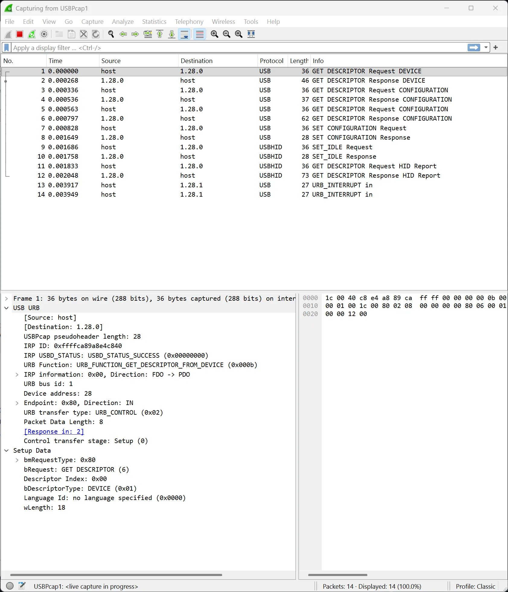
When you plug in a USB device, the host and device walk through enumeration in this sequence:
Host → Device: GET_DESCRIPTOR (Device Descriptor)
Device → Host: 18-byte Device Descriptor

Host → Device: GET_DESCRIPTOR (Configuration Descriptor)
Device → Host: Configuration + Interface + Endpoint + class-specific

The host parses this to decide: what kind of device is this? which driver?
how many endpoints? how do we talk to it?
In CubeMX, ST’s middleware pre-generates a descriptor in usbd_desc.c. But the moment you
want to customize it, say adding an interface to build a composite device, changing the HID
Report Descriptor to reshape your data, or swapping the VID/PID so the host loads the right
driver, you need to understand every field first. Get a single byte wrong and enumeration can
fail outright, or the host can end up misreading your data.
Here’s a real enumeration capture from an HID device right after being plugged in:
Device Descriptor: the big picture
The Device Descriptor is the first thing the host reads, and it’s always a fixed 18 bytes.
Here’s the real array from this project’s usbd_desc.c, with USBD_VID = 1155 (0x0483, ST
Microelectronics) and USBD_PID = 22315 (0x572B):
uint8_t USBD_HID_DeviceDesc[USB_LEN_DEV_DESC] = { 0x12, /* bLength = 18 */ USB_DESC_TYPE_DEVICE, /* bDescriptorType = 0x01 */ 0x00, 0x02, /* bcdUSB = 0x0200 (USB 2.0) */ 0xEF, /* bDeviceClass: Miscellaneous, required when using IAD */ 0x02, /* bDeviceSubClass: Common Class */ 0x01, /* bDeviceProtocol: IAD */ USB_MAX_EP0_SIZE, /* bMaxPacketSize0 = 64 bytes, valid values: 8/16/32/64 */ LOBYTE(USBD_VID), HIBYTE(USBD_VID), /* idVendor = 0x0483 */ LOBYTE(USBD_PID), HIBYTE(USBD_PID), /* idProduct = 0x572B */ 0x00, 0x02, /* bcdDevice = 0x0200 (firmware version 2.00) */ USBD_IDX_MFC_STR, /* iManufacturer, index into the String Descriptor */ USBD_IDX_PRODUCT_STR, /* iProduct */ USBD_IDX_SERIAL_STR, /* iSerialNumber */ USBD_MAX_NUM_CONFIGURATION /* bNumConfigurations = 1 */};Fields you’ll usually need to change:
-
bDeviceClass/SubClass/Protocol=0xEF/0x02/0x01: this triplet is mandatory any time your device uses IAD (a composite with CDC, for example). Get it wrong and USBView will tell you exactly what’s missing:*!*ERROR: device class should be Multi-interface Function 0xEF -
idVendor/idProduct: the most important identifier pair here. The host uses VID/PID to pick a driver.0x0483is ST’s own VID, fine for development and internal use. For a commercial product, you’ll need to buy your own VID from USB-IF. -
bcdDevice: the firmware version, in BCD.0x0200means version 2.00. This is genuinely useful for debugging, since a glance at Device Manager tells you exactly which firmware a board is running. -
iManufacturer/iProduct/iSerialNumber: indices into the String Descriptor. In this project,iProduct = "STM32 USB HID 4x4 Macro Keypad". That string shows up in Device Manager, and it’s also the stringvendor_test.pyprints when it finds the device (post 7). -
bMaxPacketSize0: not a cosmetic field. The host always reads the first 8 bytes of the Device Descriptor before anything else, purely to get this value, and only then requests the full 18 bytes. It needs to know EP0’s max packet size to correctly split up the control transfers that follow. Get this field wrong in those first 8 bytes and enumeration fails right away, with no useful error at all.
Configuration Descriptor: power and interface count
The Configuration Descriptor never stands alone. It’s the header for a much larger block
that contains every Interface and Endpoint Descriptor underneath it. When the host sends
GET_DESCRIPTOR(Configuration), the device has to return that entire block in one shot.
Here’s the header of the configuration descriptor from this project:
/* Configuration Descriptor header, 9 bytes */uint8_t USBD_CfgDesc[] = { 0x09, /* bLength = 9 */ 0x02, /* bDescriptorType = 0x02 (Configuration) */ LOBYTE(wTotalLength), HIBYTE(wTotalLength), /* wTotalLength = total size of the whole block * (Config + every Interface and Endpoint underneath) */ 0x03, /* bNumInterfaces = 3 (composite: HID + CDC Comm + CDC Data) */ 0x01, /* bConfigurationValue = 1, the ID of this config */ 0x00, /* iConfiguration, string index, 0 = none */ 0x80, /* bmAttributes: see below */ 0x32, /* bMaxPower = 0x32 = 50 x 2mA = 100mA */ /* --- Interface Descriptors and Endpoint Descriptors follow --- */};wTotalLength has to exactly match the total size of the entire descriptor chain. In
practice, the host reads a Configuration Descriptor in two steps: it reads the first 9 bytes
to get wTotalLength, then uses that value to request the full block: Config + Interface +
Endpoint + class-specific descriptors. Get this value wrong and the host either truncates the
data, reads past the end into memory that isn’t a descriptor at all, or misparses the whole
structure.
bNumInterfaces has to match the actual number of interfaces in the descriptor. If the
declared count doesn’t match reality, the host can end up ignoring the last interface or
misreading the whole composite device’s structure.
Why does one wrong byte break the entire chain?
The host has no prior knowledge of the descriptor’s structure. It reads sequentially:
- Read the current descriptor’s
bLength. - Jump forward exactly that many bytes to reach the next descriptor.
- Read
bDescriptorTypeto identify what kind of descriptor it just landed on (Interface / Endpoint). - Repeat from step 1 until it’s done.
If any descriptor in the middle has a wrong bLength, the host’s offset drifts, and
everything after that point gets misread, not just truncated at the end.
bmAttributes
This is a field that’s easy to get wrong. It’s usually one of three values:
0x80= Bus-powered, no remote wakeup support (drawing power from the USB VCC line)0xC0= Self-powered (the device has its own power source outside USB)0xA0= Bus-powered + Remote Wakeup
This series’ device declares bus-powered (0x80). If you declare Self-powered 0xC0 but
still actually draw power from USB, nothing breaks functionally. The device still runs, but
the host may miscalculate the power budget it allocates to other devices on the same bus.
bMaxPower
This one really matters for a bus-powered device.
It’s the current the device needs from the host, in 2mA units. This project declares
bMaxPower = 0x32, meaning the device needs 100mA. The math:
0x32 = 50 x 2mA = 100mAIf your board only draws power from USB, this needs to be accurate.
- Declare too little relative to actual draw and the board can run short on power.
- Declare too much and some hosts may refuse to enumerate the device if the port doesn’t have that much budget to spare.
Interface Descriptor: describing a function
Every Interface Descriptor describes one function of the device. The
bInterfaceClass/SubClass/Protocol triplet matters most here, since the host uses these
three values to pick the correct class driver:
| Value | Class Driver | Notes |
|---|---|---|
| 0x02 / 0x02 / 0x01 | CDC ACM (Virtual COM Port) | Abstract Control Model + AT Commands. Windows/Linux bind the cdc_acm driver. Used in this project. |
| 0x03 / 0x00 / 0x00 | HID, no subclass, no protocol | Custom HID, not a standard keyboard or mouse. |
| 0x03 / 0x01 / 0x01 | HID Boot Keyboard | A standard keyboard, usable by BIOS/UEFI before the OS loads a driver. Interface 0 in this project. |
| 0x03 / 0x01 / 0x02 | HID Boot Mouse | A standard mouse, and also the default descriptor CubeMX generates even when you select HID Keyboard. |
| 0x08 / 0x06 / 0x50 | Mass Storage (MSC) | SCSI + Bulk Only Transport, a USB drive. Not used in this project. |
| 0xFF / 0x00 / 0x00 | Vendor Specific | No class driver, needs WinUSB/libusbK via Zadig (post 7). Used in this project. |
This project uses three of these: HID Boot Keyboard, CDC ACM, and Vendor Specific. Mass Storage and HID Mouse aren’t part of the final composite descriptor. They’re listed above purely for a complete reference against the spec.
Endpoint Descriptor: the data channel
Every endpoint, other than EP0, needs its own Endpoint Descriptor. It describes where and how data moves between host and device for a given function.
Here’s the endpoint descriptor for the HID Boot Keyboard device:
/* Endpoint Descriptor, 7 bytes */0x07, /* bLength = 7 */0x05, /* bDescriptorType = 0x05 (Endpoint) */0x81, /* bEndpointAddress, see below */0x03, /* bmAttributes: Transfer Type, covered in post 2, 0x03 = Interrupt */0x40, 0x00, /* wMaxPacketSize = 0x0040 = 64 bytes */0x0A, /* bInterval = 10ms polling, reading this field was covered in post 2 */The field people misread most often is bEndpointAddress. Here’s its bit layout:
Direction [7] Data transfer direction
-
0 - OUT - Host → Device
-
1 - IN - Device → Host
[6:4] Always 0, unused [3:0] Endpoint number, 0-15 Bit 7 sets the transfer direction, from the device’s point of view. For example:
0x81= EP1 IN (device sends up to the host).0x01= EP1 OUT (host sends down to the device).
Two endpoints with the same number but opposite direction (EP1 IN and EP1 OUT) are two completely separate endpoints.
Endpoint addresses can’t repeat within the same configuration. STM32 Full Speed supports up to 8 endpoints (EP0 plus EP1-EP7), and each one can be IN, OUT, or both, depending on the hardware.
HID Descriptor: what makes HID different
An HID interface needs one more special descriptor, sitting between the Interface Descriptor and the Endpoint Descriptor:
/* HID Descriptor, 9 bytes (minimum) */0x09, /* bLength = 9 */0x21, /* bDescriptorType = 0x21 (HID) */0x11, 0x01, /* bcdHID = 0x0111, HID spec version 1.11 */0x00, /* bCountryCode = 0 (not localized) */0x01, /* bNumDescriptors = 1, number of Report Descriptors */0x22, /* bDescriptorType = 0x22 (Report Descriptor) */LOBYTE(HID_REPORT_DESC_SIZE), HIBYTE(HID_REPORT_DESC_SIZE), /* wDescriptorLength */The host reads this to find out how long the Report Descriptor is, then sends
GET_DESCRIPTOR(Report) separately to fetch the actual Report Descriptor.
Order matters inside the Configuration Descriptor:
Interface Descriptor (HID)
HID Descriptor          ← right after Interface, before Endpoint
Endpoint Descriptor (Interrupt IN)
Get this order wrong and the host either misparses it or never gets the HID Report Descriptor at all.
wDescriptorLength
wDescriptorLength has to exactly match the real report descriptor array’s size. Get it
wrong and the host reads too many or too few bytes, misparses the report structure, or
rejects the device outright during enumeration.
bCountryCode
bCountryCode tells the host whether this HID device was designed for a specific local
keyboard layout. A value of 0x00 means not localized, meaning the device isn’t
declaring any particular country or layout.
With an HID keyboard, firmware never sends characters like A, @, #, or ~ directly.
It sends a Usage ID from Usage Page 0x07 (Keyboard/Keypad). The OS then maps that
Usage ID to an on-screen character based on whatever keyboard layout the user currently has
selected (US, Japanese, Vietnamese, German, and so on).
So bCountryCode shouldn’t be read as “change this field and the host switches keyboard
layout.” On most modern operating systems, the actual layout is still decided by the OS or
the input method. This field is mainly there to declare that the keyboard hardware itself was
localized for a specific country or layout. For a simple macro keypad or HID keyboard like
this project’s, leaving bCountryCode = 0x00 is a safe and common choice.
IAD (Interface Association Descriptor)
IAD is required any time a composite device includes CDC on Windows. It groups the two CDC interfaces (Comm and Data) into a single function, so Windows loads the right driver and creates a COM port.
Here’s the IAD descriptor describing the CDC class, inside the Configuration Descriptor:
0x08, /* bLength */0x0B, /* bDescriptorType = IAD */0x01, /* bFirstInterface = 1 (IF1 = CDC Comm) */0x02, /* bInterfaceCount = 2 (IF1 + IF2) */0x02, /* bFunctionClass = CDC */0x02, /* bFunctionSubClass = ACM */0x01, /* bFunctionProtocol = AT Commands */0x00,As mentioned earlier, the Device Descriptor also needs the correct
bDeviceClass/SubClass/Protocol triplet. Without IAD, or if bDeviceClass isn’t 0xEF,
Windows won’t recognize the two CDC interfaces as belonging to the same function. It won’t
assign the right driver, and it won’t create a COM port for the device.
This section only covers IAD’s role in the descriptor. How IAD actually gets built into the
real composite descriptor, how wTotalLength/bNumInterfaces get updated, and the real bugs
hit while writing the composite class all live on the
Composite Device project page.
HID Report Descriptor: the language for describing data
This is the most complex and, honestly, the most interesting part of HID. The Report Descriptor doesn’t describe hardware. It describes the structure of the data packets a device sends and receives. The host reads it once during enumeration and from then on knows how to interpret every byte in every report that follows, without needing a dedicated driver per device.
Syntax: item format
Every item in a Report Descriptor is 1 to 5 bytes long:
Byte 0: Tag (bits 7..4) | Type (bits 3..2) | Size (bits 1..0)
  Size: 00=0 bytes, 01=1 byte, 10=2 bytes, 11=4 bytes
Byte 1..n: Data (if Size > 0)
For example, 0x05, 0x01:
0x05= tag=0000 (Usage Page), type=01 (Global), size=01 (1 byte of data)0x01= value = 0x01 (Generic Desktop Controls)
The item types that matter
Global items, apply to every field that follows until they change:
0x05, xx  → Usage Page        : the namespace for Usage values
0x15, xx  → Logical Minimum   : the smallest value a data field can hold
0x25, xx  → Logical Maximum   : the largest value
0x75, xx  → Report Size       : bits per field
0x95, xx  → Report Count      : number of fields
0x85, xx  → Report ID         : an ID placed at the start of the report (if used)
Local items, apply only to the next item:
0x09, xx  → Usage             : what this specific field means
0x19, xx  → Usage Minimum     : used when defining a range
0x29, xx  → Usage Maximum
Main items, these actually create a field:
0x81, xx  → Input      : a field the device sends up to the host (IN)
0x91, xx  → Output     : a field the host sends down to the device (OUT)
0xA1, xx  → Collection : groups fields together
0xC0      → End Collection
The data byte on Input/Output:
0x02 = Data, Variable, Absolute
  Data     : can change (as opposed to Constant)
  Variable : each field is its own independent value (as opposed to Array)
  Absolute : an absolute value (as opposed to Relative)
0x03 = Constant (padding, unused, just there for byte alignment)
0x06 = Data, Variable, Relative (used for delta movement, like a mouse)
Usage Page: a namespace for Usage values
A Usage Page works like a namespace in programming. The same Usage value (0x30, say) means
something different depending on which Usage Page it’s under:
Usage Page 0x01 (Generic Desktop): 0x30 = X axis
Usage Page 0x09 (Button):          0x30 = Button 48
Usage Pages you’ll run into often:
0x01 = Generic Desktop Controls (X/Y/Z, mouse, keyboard, joystick)
0x07 = Keyboard/Keypad
0x08 = LEDs
0x09 = Buttons
0x0D = Digitizer (touchscreen, pen)
0xFF = Vendor Defined (custom, no standard meaning)
The full keycode table for Usage Page 0x07 (a-z, digits, function keys, and more) is far bigger than this post has room for. See What Are HID Usage Tables? for the full reference.
Collection: grouping related fields
0xA1, 0x01  → Collection (Application) : the top-level group, every HID device needs at least one
0xA1, 0x02  → Collection (Logical)     : a logical grouping inside an Application
0xA1, 0x00  → Collection (Physical)    : groups data coming from the same physical location
0xC0        → End Collection
Reading an HID Mouse Report Descriptor byte by byte
A mouse is the classic example for seeing this syntax in action. Here’s the default report descriptor CubeMX generates for a USB HID device:
static uint8_t HID_MOUSE_ReportDesc[] = { 0x05, 0x01, /* Usage Page (Generic Desktop Controls) */ 0x09, 0x02, /* Usage (Mouse) */ 0xA1, 0x01, /* Collection (Application) */ 0x09, 0x01, /* Usage (Pointer) */ 0xA1, 0x00, /* Collection (Physical) */ 0x05, 0x09, /* Usage Page (Button) */ 0x19, 0x01, /* Usage Minimum (Button 1) */ 0x29, 0x03, /* Usage Maximum (Button 3) */ 0x15, 0x00, /* Logical Minimum (0), button released */ 0x25, 0x01, /* Logical Maximum (1), button pressed */ 0x95, 0x03, /* Report Count (3), 3 buttons */ 0x75, 0x01, /* Report Size (1), 1 bit per button */ 0x81, 0x02, /* Input (Data, Variable, Absolute) */ /* → 3 bits: [btn3][btn2][btn1] */ 0x95, 0x01, /* Report Count (1) */ 0x75, 0x05, /* Report Size (5), 5-bit padding */ 0x81, 0x03, /* Input (Constant), padding to byte */ /* → 5 bits: [0][0][0][0][0] */ 0x05, 0x01, /* Usage Page (Generic Desktop) */ 0x09, 0x30, /* Usage (X) */ 0x09, 0x31, /* Usage (Y) */ 0x09, 0x38, /* Usage (Wheel) */ 0x15, 0x81, /* Logical Minimum (-127) */ 0x25, 0x7F, /* Logical Maximum (127) */ 0x75, 0x08, /* Report Size (8), 8 bits per axis */ 0x95, 0x03, /* Report Count (3), X, Y, Wheel */ 0x81, 0x06, /* Input (Data, Variable, Relative) */ /* → 3 bytes: X delta, Y delta, Wheel */ 0xC0, /* End Collection (Physical) */ 0xC0, /* End Collection (Application) */};The report packet ends up structured like this:
Byte 0: [pad5][btn3][btn2][btn1]  ← 3 button bits + 5 padding bits
Byte 1: X movement (-127..+127)   ← signed delta
Byte 2: Y movement (-127..+127)
Byte 3: Wheel (-127..+127)
4 bytes per report, total. The host parses this correctly just from reading the descriptor, no dedicated parser needed for each different mouse.
Boot Keyboard: a fixed Boot Protocol format
With the mouse example above, the host has to read the Report Descriptor to know what fields the report contains: which bit is a button, which byte is X/Y/Wheel. A Boot Keyboard needs a slightly different understanding.
An HID Boot Keyboard still needs a valid Report Descriptor. The OS can still read it while running in Report Protocol. But because this keyboard declares itself as a Boot Keyboard, it also has to support a second, fixed report format called Boot Protocol.
The Boot Keyboard IN report format is 8 bytes:
Byte 0: modifier bitmap
Byte 1: reserved (0x00)
Byte 2: keycode[0]
Byte 3: keycode[1]
Byte 4: keycode[2]
Byte 5: keycode[3]
Byte 6: keycode[4]
Byte 7: keycode[5]
Byte 0 holds the modifier keys:
[7] Right Windows/Cmd [6] Right Alt [5] Right Shift [4] Right Ctrl [3] Left Windows/Cmd [2] Left Alt [1] Left Shift [0] Left Ctrl Each bit is its own independent modifier key: 1 means pressed, 0 means not pressed.
Multiple modifiers can be 1 at once, Ctrl+Shift, for example.
Byte 2-7 holds up to 6 keycodes currently pressed at once. That’s why the Boot Keyboard
report is often called an 8-byte keyboard report, or a 6KRO report. On key release, firmware
needs to send an empty report, all 8 bytes set to 0x00, so the host knows the key has been
released.
The important part is that Boot Protocol doesn’t let firmware change this format on a whim. The reason is that BIOS/UEFI, or firmware running before the OS has loaded a full driver, usually can’t parse a complex HID Report Descriptor. All it needs to know is: if this is a Boot Keyboard, just read the fixed 8-byte report described above.
The host can switch between the two modes with the HID class request SET_PROTOCOL:
wValue = 0  → Boot Protocol
wValue = 1  → Report Protocol
Here’s where it’s easy to get confused: bInterfaceSubClass = 0x01 and bInterfaceProtocol
in the descriptor are not the protocol currently running. They only declare that this
interface supports Boot Protocol, more like an advertisement of capability. Which protocol
is actually active is separate runtime state, toggled through the SET_PROTOCOL control
transfer, and firmware has to keep its own variable to answer correctly when the host asks
via GET_PROTOCOL.
Per spec, the default right after enumeration is Report Protocol. In practice though:
- BIOS/UEFI (without a full HID driver yet) usually sends
SET_PROTOCOL(0)during POST to switch to Boot Protocol. Some older BIOSes don’t even bother sending that and just assume the device is already in Boot Protocol, a common legacy behavior even if it doesn’t strictly follow spec. - Once the OS loads its full HID driver, it typically sends
SET_PROTOCOL(1)to switch back to Report Protocol and starts parsing the device’s own Report Descriptor.
So if you want to do this properly in firmware, the device should track its current protocol
state and respond accordingly. For this simple keypad project, the Report Descriptor already
describes the standard 8-byte keyboard format, so the same report buffer works for both
modes. Even so, firmware should still handle SET_PROTOCOL correctly, since the host is
entitled to send that request.
In the Interface Descriptor, this triplet tells the host it’s looking at an HID Boot Keyboard:
bInterfaceClass    = 0x03  // HID
bInterfaceSubClass = 0x01  // Boot Interface Subclass
bInterfaceProtocol = 0x01  // Keyboard
This is also a spot where CubeMX likes to generate the wrong value. If
bInterfaceProtocol = 0x02, the host reads this interface as a Boot Mouse instead of a Boot
Keyboard. That’s exactly the descriptor bug hit at the lab-08 milestone.
The full 8-byte report structure, with real modifier/keycode examples from this project, is covered in post 5, HID Keyboard Baseline.
Building a descriptor one step at a time
The safest way to write a descriptor isn’t to write out every interface you’ll ever need and then plug it in for the first time. With that many interfaces at once, tracking down a bug becomes slow and imprecise. Adding one interface at a time costs a bit more time upfront but pays off heavily in debugging. After finishing one interface, plug in and check the descriptor with USBView before adding the next:
Step 1: A simple device, 1 interface        → confirm enumeration works
Step 2: Add a second interface (e.g. CDC)   → confirm bNumInterfaces, IAD if needed
Step 3: Add a third interface and beyond    → confirm the new wTotalLength, new endpoints
The reason to go step by step is that a broken descriptor often doesn’t produce a clear error
at all, it usually just shows up as a generic “Unknown USB device.” Some mistakes (a wrong
bNumInterfaces, a misplaced HID Descriptor, a broken IAD) still let the device enumerate,
and only cause problems once a driver actually tries to use that interface. If you add an
interface, fix wTotalLength/bNumInterfaces, and touch several other things all at once,
your debugging surface gets huge. Add exactly one interface at a time instead, and whatever
breaks next is almost certainly in the part you just added.
This also means a descriptor is rarely “done” on the first pass. Every time you add an
interface, wTotalLength and bNumInterfaces both need updating again. The same principles
covered above (reading sequentially by bLength, IAD’s role, the HID Descriptor needing to
sit before the Endpoint Descriptor) all still apply, just with new numbers for the new
structure.
Summary
The descriptor decides everything. The host knows nothing about your source code and
doesn’t guess at firmware’s intent. It only reads a sequential, self-describing byte stream
that firmware provides, from the Device Descriptor down to the Report Descriptor, and uses
that to identify and validate the connected device. The fixed hierarchy (Device contains
Configuration, Configuration contains Interface and Endpoint) and the way the host reads it
sequentially via bLength/bDescriptorType are the essential foundation for the rest of this
series.
HID adds one more descriptive layer on top, the HID Report Descriptor. It tells the host how to read every byte in a report, with each bit and byte spelled out explicitly. This mechanism applies to every HID device, universally.
If a device declares itself a Boot Keyboard or Boot Mouse, it needs to support a second, fixed format called Boot Protocol. This format is used in environments without a full HID driver yet, like BIOS or UEFI. In those environments, the host can’t read or understand an HID Report Descriptor at all, so it relies purely on Boot Protocol’s fixed structure to get keyboard or mouse data.
HID Report Descriptor and Boot Protocol exist side by side. Neither replaces the other, and it’s easy to conflate them since both describe reports from the same device. But they serve two entirely different situations. The HID Report Descriptor is for a host that already knows how to read and interpret descriptors. Boot Protocol is for a host that doesn’t have that ability yet.
The concepts covered here, IAD, the HID Descriptor needing to come before the Endpoint, how to
calculate wTotalLength, and a composite device’s bDeviceClass, all come back repeatedly in
later posts once we get into real implementation, with concrete examples and measured results
from the actual project.
The next post covers the key input pipeline, the firmware layer sitting behind the keyboard, before we get anywhere near the USB transport layer.
References
- USB 2.0 Specification, Chapter 9: Device Framework, descriptor structure
- USB in a NutShell, Chapter 5: Descriptors
- HID Class Specification 1.11, HID Descriptor and Report Descriptor format
- HID Usage Tables 1.5, Usage Page and Usage values
- STM32G0B1 Reference Manual RM0444, USB DRD_FS, PMA layout
- USB Device Tree Viewer, for parsing and displaying descriptors
- What Are HID Usage Tables?, for looking up Usage IDs and keycodes
- What Is the HID Keyboard Report Format?, modifier byte, keycode array, bCountryCode
- What Is the USB Enumeration Process?, the full 7-step enumeration flow
- What Is a USB Descriptor Overview?, a quick reference for the descriptor hierarchy
Found this article useful?
Share, give feedback, or support if you find this content valuable.