MDX Components Showcase for Firmware Articles
A reference article showing how to use callouts, diagrams, timelines, checklists, images, tables and file trees in BIOS/embedded blog posts.
This article is a reference page for writing future BIOS, UEFI and embedded firmware posts. You can copy the component examples below into any MDX article.
Callout styles
Use callouts when you want to highlight a note, a warning, a debug hint or an important firmware rule. The new callout style is stronger than the previous soft version, but still quiet enough for both light and dark mode.
<Callout type="important" titleKey="calloutUefiRule" lang="en">
Boot Services are only valid before `ExitBootServices()`.
</Callout><Callout type="debug" variant="stripe" lang="en">
Check DSC/FDF and Depex when a DXE driver is not dispatched.
</Callout><Callout type="warning" variant="compact" lang="en">
Use compact callouts for short warnings.
</Callout>Available types:
note / tip / warning / danger / important / debug / successSupported languages for default labels:
lang="vi" / lang="en" / lang="ja"Flow diagram
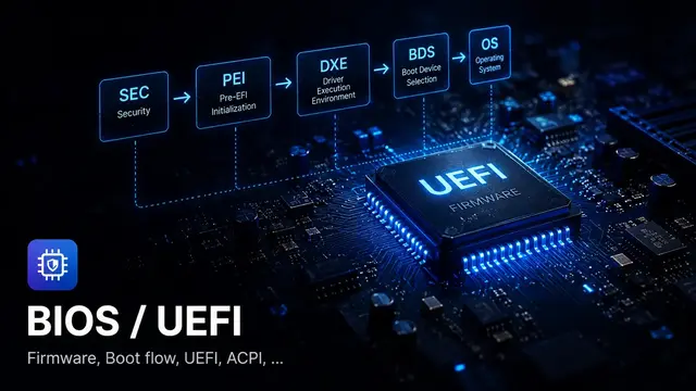
Use FlowDiagram when explaining boot flow, USB enumeration, firmware update sequences or task communication.
Temporary CPU setup
The platform starts from the reset vector and prepares a minimal execution environment.
Memory initialization
PEIMs initialize DRAM and produce HOBs for later phases.
Driver execution
DXE drivers install protocols and build the handle database.
Boot selection
The boot manager selects a boot option and loads the OS loader.
<FlowDiagram
  steps={[
    { label: 'SEC', title: 'Temporary CPU setup', description: '...' },
    { label: 'PEI', title: 'Memory initialization', description: '...' },
    { label: 'DXE', title: 'Driver execution', description: '...' },
    { label: 'BDS', title: 'Boot selection', description: '...' }
  ]}
/>
Step timeline
Use StepTimeline for debug procedures or implementation sequences. The new layout is intentionally compact so it does not create excessive empty space.
Confirm the module is included in the firmware image
Check the DSC and FDF files, then confirm the driver appears in the generated FV.
Check dependency expression
If Depex is not satisfied, the DXE dispatcher will not start the driver.
Check protocol installation
Use debug logs or UEFI Shell tools to confirm the expected protocol exists.
<StepTimeline
  lang="en"
  steps={[
    { title: 'Confirm DSC/FDF', description: '...' },
    { title: 'Check Depex', description: '...' },
    { title: 'Check protocol installation', description: '...' }
  ]}
/>
Interactive checklist
Use CheckList when you want readers to follow a debugging or implementation checklist. It can be ticked directly in the browser and persists with localStorage by default.
DXE driver debug checklist
Tick each item while debugging. The checked state is saved locally in the browser.
0/4 completed
<CheckList
  id="dxe-debug-checklist"
  title="DXE driver debug checklist"
  lang="en"
  items={[
    { text: 'Confirm DSC reference', note: 'The module must be built.' },
    { text: 'Check Depex', note: 'Required protocols must exist.' }
  ]}
/>
Article image
Use ArticleImage for one main diagram or screenshot.
<ArticleImage
  src="/images/topics/bios-uefi.webp"
  alt="BIOS and UEFI firmware chip illustration"
  caption="A single article image with caption."
/>
Image grid
Use ImageGrid when comparing two or three screenshots or diagrams.
BIOS / UEFI
Embedded firmware
Debugging tools
<ImageGrid
  columns={3}
  images={[
    { src: '/images/topics/bios-uefi.webp', alt: '...', caption: 'BIOS / UEFI' },
    { src: '/images/topics/embedded-firmware.webp', alt: '...', caption: 'Embedded firmware' },
    { src: '/images/topics/tools-debugging.webp', alt: '...', caption: 'Debugging tools' }
  ]}
/>
Image with text
Use ImageText when a screenshot needs explanation next to it.
When to use this layout
This component is useful for explaining a screenshot, a register view, a debug log, a board photo or a firmware architecture diagram.
Keep the text short. If the explanation becomes long, use a normal section instead.
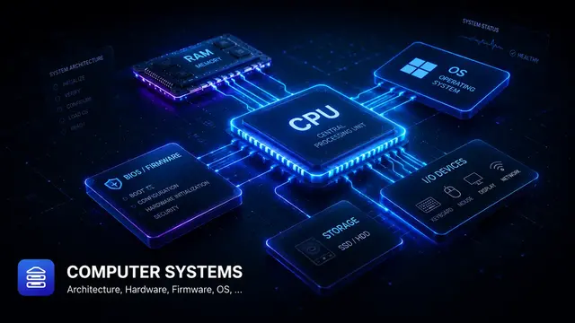
<ImageText src="/images/topics/computer-systems.webp" alt="..." imagePosition="right">
  ### When to use this layout
  Short explanation goes here.
</ImageText>
Spec table
Use SpecTable for field descriptions, descriptor layouts or firmware configuration tables.
| Field | Value | Note |
|---|---|---|
| BootOrder | UINT16[] | Defines the boot option order used by BDS. |
| BootNext | UINT16 | Overrides the next boot only. |
| Boot#### | EFI_LOAD_OPTION | Stores one boot option entry. |
<SpecTable
  lang="en"
  rows={[
    { field: 'BootOrder', value: 'UINT16[]', note: '...' },
    { field: 'BootNext', value: 'UINT16', note: '...' }
  ]}
/>
File tree
Use FileTree when documenting a source tree or firmware package structure.
EDK2 package example
MyPkg/
+- MyPkg.dec
+- MyPkg.dsc
+- MyPkg.fdf
+- Drivers/
   +- SampleDxe/
      +- SampleDxe.inf
      +- SampleDxe.c
<FileTree
title="EDK2 package example"
files={[
'MyPkg/',
'+- MyPkg.dec',
'+- Drivers/SampleDxe/SampleDxe.inf'
]}
/>Recommended writing pattern
For a technical article, a good structure is:
Before publishing
0/4 completed
Found this useful?
Save it or share it with someone learning firmware, BIOS/UEFI, and embedded systems.
Nội dung liên quan
Một số bài viết, ghi chú hoặc project có liên quan đến nội dung bạn vừa đọc.
What is BIOS Setup Variable?
Quick note explaining BIOS Setup Variable for BIOS/UEFI and embedded firmware readers.
What is Flash Descriptor?
Quick note explaining Flash Descriptor for BIOS/UEFI and embedded firmware readers.
What is Secure Boot User Mode?
Quick note explaining Secure Boot User Mode for BIOS/UEFI and embedded firmware readers.
Đọc thêm về BIOS/UEFI
Khám phá các bài viết về BIOS/UEFI, embedded firmware, debugging và system-level thinking.